Two years ago, I bought a Kindle Touch. At the time, I couldn’t find a case that was cheap, light and durable, so I decided to make my own. I settled on leather as the main material, due to its durability and workability. The design is simple and consists of three parts
a 35cm x 12cm ‘cover’ that wraps around the height of the Kindle. This part also includes the brace holding the bottom of the Kindle in place.
two 17cm x 12cm pieces to provide extra protection for the front and back (I ended up only making one of these for the back).
a 19cm x 2cm strap to hold the top of the Kindle in the case.
I made a parchment paper and staples prototype and headed to a small leather workshop in the town where I lived. The owner was extremely helpful and kindly took the time to explain various aspects of leather work to a complete novice. I took my baking paper model to buy the required leather and she pointed out some problems to do with the assembly and even gave me some leather samples for free to build a first mock-up. A couple of lessons learned from the prototype:
punch the holes through the front of the case in hopes of making them align better.
use a thicker thread to obscure any ill positioned holes.
make the fit too tight rather than too loose as leather has some give in it.
I drew the shape of the individual pieces onto the back of the leather with a ballpoint pen and used a utility knife to cut them out. Proper scissors would have made this much easier but the utility knife combined with a ruler to keep the cut straight worked fine for me. By far the most challenging and time consuming part of making the case was punching the ~150 holes through up to 3 layers of leather. I used a hammer and a pointy tool (similar to this one). It was tough to make the holes the same size but with a bit of practice the results were decent. Leather is mildly forgiving of measurement inaccuracies which was extremely helpful when sewing the pieces together.
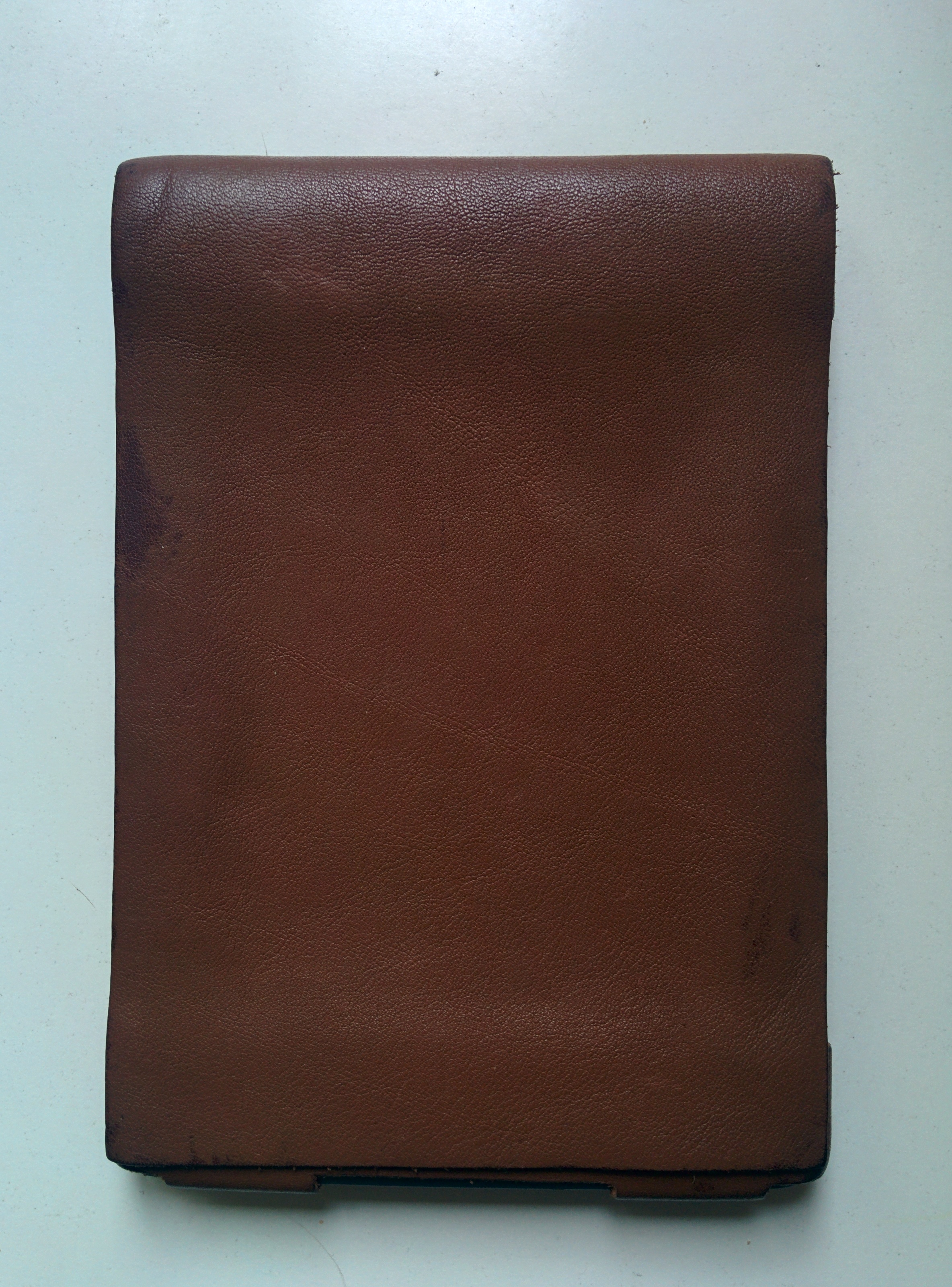
The added thickness of the case actually makes reading with the Kindle much easier as it is far more comfortable to hold. The case weighs ~60 grams, so it adds 20% to the overall weight. I originally wanted to add a magnet to hold the front cover in place, and another layer of leather to reinforce the front cover, but never got around to it. Here’s what it looks like today:
Total cost: 10EUR Total time spent: ~10hrs (planning, trips to the shop, 2 prototypes and the final product).
While there are cheaper (and less time consuming!) options available on Amazon, it was fun to plan and make my own! It turned out to be very sturdy too: it has survived a good two years so far with little sign of wear, while my friend’s case (who bought his at the same time as I made my own) is falling apart.
When cycling, I regularly use my smartphone to check whether I’m still going in the right direction. The frequent GPS-usage has the downside that my phone runs out of juice very quickly. This problem is exasperated on longer trips, where finding a power outlet isn’t always guaranteed. Hence, I needed a way to recharge my phone on the fly or at least to reduce the discharge rate of its battery.
The idea: charge your phone whilst cycling, using your idling hub dynamo!
It seems as though many have already thought of this but I couldn’t find any commercial products and so decided to try my hand at some DIY electronics. My bicycle has a Shimano DH-3N30 hub dynamo, which doesn’t do much most of the time I’m cycling and will be re-purposed to charge my phone.
Luckily, there are some very good instructions flying around the internet. I found this blog post and its comments very informative. Much of the information therein and in this post is based on information in this forum post by Simon Galgut.
Armed with some vague knowledge and enthusiasm, let’s get started:
Note: I am providing these instructions without any warranties. There may be errors and if your phone blows up because of them, I am in no way responsible! Try at your own risk!
Requirements:
I’ve got 2 main objectives for this project. It has to:
conform to the USB specification so it’s safe to charge most smartphones.
be able to switch between headlights and the charging circuit. Winter is coming and I don’t want to have to pedal in the dark.
The hub dynamo generates AC power, which will need to be rectified to DC and then controlled to make charging delicate electronics safe. Smartphones have a charging circuit built-in – so there is no need to worry about overcharging the battery – but the supply voltage must be 5V [1]. I want to make my charger confirm to the USB specification, which allows a device to draw up to 500mA at 5V [2].
The dynamo:
It turns out that it’s tough to dig up a proper datasheet for the Shimano DH-3N30. I don’t want to open mine up to poke around the insides and risk breaking it. If anyone has a link to one, please share it in the comments. The DH-3N30 generates up to 3W of AC power at 6V [3]. I’ve counted the poles by counting the ‘cogs’ when spinning the wheel for one revolution: there are 28.
Rectifier circuit:
The first step is to rectify the AC coming from the dynamo [4]. We’ll be using a bridge rectifier since these are cheaply available and have a small size.
Normal AC voltage
Rectified voltage
Rectified and smoothed voltage
After adding a shunt capacitor across the regulated DC line and ground, we obtain a voltage like the one shown in the picture above. The remaining ripple in the DC voltage can be seen in the diagram above. We want to reduce this as much as possible to safeguard delicate phone electronics! This is can be accomplished by changing the capacitor value as we will see.
The equation for the ripple voltage is:
Eqn. 1
With a dynamo, the problem is that the frequency will change depending on how fast one cycles. If cruising along at 10km/h, the wheel and dynamo will spin significantly slower than if cycling down a hill at 50km/h.
The cruising scenario is probably the lowest speed the charging circuit should work at. We need to make sure that the ripple voltage in Eqn. 1 stays acceptably low. The frequency of the alternating current produced is by my dynamo can be calculated as follows:
Eqn. 2
Where N is the rotational velocity of the dynamo, P the number of poles and f is the frequency of oscillation of the generated AC. At a speed of 3m/s (10.8km/h), my bicycle wheel spins at around 79 rpm. Assuming that I counted right and the DH-3N30 has 28 poles,
Eqn. 3
Substituting that and the wanted current (500mA) and the value of my large capacitor (2.2F) into Eqn. 1 yields a ripple voltage of 0.0123V. Consequently, the supply voltage should be between 6 and ~5.99V.
The rectified and smoothed DC will then need to be regulated down to 5V using a voltage regulator such as the LM2940. This should theoretically result in perfectly smooth 5VDC.
Some refinement:
I have added a SPTT switch to switch the whole circuit off or power the charger or the headlights from the handlebar.
The circuit:
The circuit diagram
If you are wondering where C2 and C3 come from, they are specified in the LM2940 datasheet and are required for the voltage regulator to work correctly. If you use a different voltage regulator, you will probably need capacitors with different values.
Here’s the list of parts I’ve used. Note that some items have a minimum order size of 5 but you might be able to find them somewhere else.
The total cost comes to £10.69 and you’ll have some parts to spare if you accidentally blow a capacitor. I find Farnell quite useful as they usually have links to the components’ datasheet but note that they have a minimum order size of £20. You could also try a local Maplin’s for some of these parts. In any case, this should give you an idea of what you need.
You will also need some wire and a bit of vero board, a soldering iron, solder and some basic tools.
Actual tinkering:
After a bit of soldering, this is the end product. I haven’t optimised spacing at all yet, that will come later. It works, which is the main thing!
The final assembly
A closeup of the rectifier and smoothing circuit
So, lets do some testing and see what happens!
This first video shows the regulated voltage put out by the circuit: a constant 4.99V! The fluctuation in the volt reading at lower speeds can probably be attributed to my uneven wheel spinning. As you can see from the speedometer readings, a stable voltage can be expected at speeds above 8km/h.
The second video shows the charger in action. It works!
Coming soon:
There are still several improvements I would like to make to my phone charger, namely:
Reduce the overall footprint and mount it on the bicycle.
Fabricate a male plug for the headlights connector.
I need to do some in-depth testing of the circuit under different conditions to see how it holds up.
References:
[1] This is the case for almost all smartphones available. If your smartphone can be charged using your computer via a USB port, then this should work for you.
 I made a parchment paper and staples prototype and headed to a small leather workshop in the town where I lived. The owner was extremely helpful and kindly took the time to explain various aspects of leather work to a complete novice. I took my baking paper model to buy the required leather and she pointed out some problems to do with the assembly and even gave me some leather samples for free to build a first mock-up. A couple of lessons learned from the prototype:


 Total cost: 10EUR Total time spent: ~10hrs (planning, trips to the shop, 2 prototypes and the final product).


