Charging USB devices from a hub dynamo
When cycling, I regularly use my smartphone to check whether I’m still going in the right direction. The frequent GPS-usage has the downside that my phone runs out of juice very quickly. This problem is exasperated on longer trips, where finding a power outlet isn’t always guaranteed. Hence, I needed a way to recharge my phone on the fly or at least to reduce the discharge rate of its battery.
The idea: charge your phone whilst cycling, using your idling hub dynamo!
It seems as though many have already thought of this but I couldn’t find any commercial products and so decided to try my hand at some DIY electronics. My bicycle has a Shimano DH-3N30 hub dynamo, which doesn’t do much most of the time I’m cycling and will be re-purposed to charge my phone.
Luckily, there are some very good instructions flying around the internet. I found this blog post and its comments very informative. Much of the information therein and in this post is based on information in this forum post by Simon Galgut.
Armed with some vague knowledge and enthusiasm, let’s get started:
Note: I am providing these instructions without any warranties. There may be errors and if your phone blows up because of them, I am in no way responsible! Try at your own risk!
Requirements:
I’ve got 2 main objectives for this project. It has to:
- conform to the USB specification so it’s safe to charge most smartphones.
- be able to switch between headlights and the charging circuit. Winter is coming and I don’t want to have to pedal in the dark.
The hub dynamo generates AC power, which will need to be rectified to DC and then controlled to make charging delicate electronics safe. Smartphones have a charging circuit built-in – so there is no need to worry about overcharging the battery – but the supply voltage must be 5V [1]. I want to make my charger confirm to the USB specification, which allows a device to draw up to 500mA at 5V [2].
The dynamo:
It turns out that it’s tough to dig up a proper datasheet for the Shimano DH-3N30. I don’t want to open mine up to poke around the insides and risk breaking it. If anyone has a link to one, please share it in the comments. The DH-3N30 generates up to 3W of AC power at 6V [3]. I’ve counted the poles by counting the ‘cogs’ when spinning the wheel for one revolution: there are 28.
Rectifier circuit:
The first step is to rectify the AC coming from the dynamo [4]. We’ll be using a bridge rectifier since these are cheaply available and have a small size.

Normal AC voltage

Rectified voltage

Rectified and smoothed voltage
After adding a shunt capacitor across the regulated DC line and ground, we obtain a voltage like the one shown in the picture above. The remaining ripple in the DC voltage can be seen in the diagram above. We want to reduce this as much as possible to safeguard delicate phone electronics! This is can be accomplished by changing the capacitor value as we will see.
The equation for the ripple voltage is:

Eqn. 1
With a dynamo, the problem is that the frequency will change depending on how fast one cycles. If cruising along at 10km/h, the wheel and dynamo will spin significantly slower than if cycling down a hill at 50km/h.
The cruising scenario is probably the lowest speed the charging circuit should work at. We need to make sure that the ripple voltage in Eqn. 1 stays acceptably low. The frequency of the alternating current produced is by my dynamo can be calculated as follows:

Eqn. 2
Where N is the rotational velocity of the dynamo, P the number of poles and f is the frequency of oscillation of the generated AC. At a speed of 3m/s (10.8km/h), my bicycle wheel spins at around 79 rpm. Assuming that I counted right and the DH-3N30 has 28 poles,

Eqn. 3
Substituting that and the wanted current (500mA) and the value of my large capacitor (2.2F) into Eqn. 1 yields a ripple voltage of 0.0123V. Consequently, the supply voltage should be between 6 and ~5.99V.
The rectified and smoothed DC will then need to be regulated down to 5V using a voltage regulator such as the LM2940. This should theoretically result in perfectly smooth 5VDC.
Some refinement:
I have added a SPTT switch to switch the whole circuit off or power the charger or the headlights from the handlebar.
The circuit:

The circuit diagram
If you are wondering where C2 and C3 come from, they are specified in the LM2940 datasheet and are required for the voltage regulator to work correctly. If you use a different voltage regulator, you will probably need capacitors with different values.
Here’s the list of parts I’ve used. Note that some items have a minimum order size of 5 but you might be able to find them somewhere else.
| Symbol | Item | Example | Cost |
| C1 | 2200 µF capacitor | Farnell 9693629 | £2.20 (5) |
| VR | LM2940-CT 5V regulator | Farnell 9490191 | £2.02 |
| C2 | 0.47 µF capacitor | Farnell 1457606 | £1.21 (5) |
| C3 | 22 µF capacitor | Farnell 1457616 | £1.21 (5) |
| BR | Bridge rectifier | Farnell 9381449 | £1.55 (5) |
| SPTT switch | Farnell 9381449 | £1.55 (5) | |
| Shimano hub connector | Ebay | £2.50 |
The total cost comes to £10.69 and you’ll have some parts to spare if you accidentally blow a capacitor. I find Farnell quite useful as they usually have links to the components’ datasheet but note that they have a minimum order size of £20. You could also try a local Maplin’s for some of these parts. In any case, this should give you an idea of what you need.
You will also need some wire and a bit of vero board, a soldering iron, solder and some basic tools.
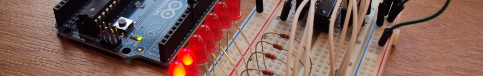
Actual tinkering:
After a bit of soldering, this is the end product. I haven’t optimised spacing at all yet, that will come later. It works, which is the main thing!

The final assembly

A closeup of the rectifier and smoothing circuit
So, lets do some testing and see what happens!
This first video shows the regulated voltage put out by the circuit: a constant 4.99V! The fluctuation in the volt reading at lower speeds can probably be attributed to my uneven wheel spinning. As you can see from the speedometer readings, a stable voltage can be expected at speeds above 8km/h.
The second video shows the charger in action. It works!
Coming soon:
There are still several improvements I would like to make to my phone charger, namely:
- Reduce the overall footprint and mount it on the bicycle.
- Fabricate a male plug for the headlights connector.
- I need to do some in-depth testing of the circuit under different conditions to see how it holds up.
References:
[1] This is the case for almost all smartphones available. If your smartphone can be charged using your computer via a USB port, then this should work for you.

Great write-up! I would be interested to know if you can make the circuit more efficient, as the next generation of phones suck up more and more power! I still use this circuit with a few variations all without a headlight switch and works beautifully.
Thanks Arend, your blog was extremely helpful! I’m currently working on a logging solution to monitor voltages around the circuit and the current flowing into the phone. Once that’s done, I’ll have a better idea how efficient the circuit is and work to improve it.
this is great, but still not quite what I’ve been looking for…. I’ve been looking for a design that can charge a NiMH battery from the dynamo when it’s running, and then at the same time drive a cree or USB… the advantage would be that it gives you full power standlight functionality, and the ability to run a smartphone for GPS mapping/recording, whatever… Have you considered something like that? Today I’m just running the dynamo into a bridge rectifier to drive the cree directly… -lj
This is something I’m working on, actually. Adding batteries makes the project much more complex, though, as the charge levels needs to be monitored to avoid overcharging and there needs to be a way to switch source from the dynamo to the battery when standing still. Hopefully I’ll find some time to put it together over christmas.
At the end of the day though, the main problem is how much current the dynamo can generate. Based on some crude measurements, I’m getting around 300-400mA out of this circuit at ~25km/h. That’s not even really enough to charge the phone on its own, let alone together with batteries. Perhaps there is a way to draw more current or, as Arend suggested, improve the efficiency of the circuit above.
“At the end of the day though, the main problem is how much current the dynamo can generate.” Spot on. If you have a 3 Watt hub dynamo you will get no more then 500 mA at 6 volt (at best), that’s without any ac/dc conversion. I have measured this raw AC performance and it shows there is not much room for making it more efficient. To make matters worse many hub dynamo’s are only 2.4 Watt
Pingback: Arduino Potential difference & Current measurements with logging « parttimetinkerer
Here is a product:
http://www.miniwiz.com/en/products/transportation/reecharge
Always someone ahead, but homebrew is more fun.
I hadn’t come across that before, thanks! From the site: “This product has been discontinued”… maybe there just isn’t a big enough market for this type of product. That look pretty much like what I want to make, though!
I’ve been thinking about this for a buddy with a Nexus hub that works on his bike. Glad I found your blog. I saw the UNO on your page and got excited that I finally found a need to get one 🙂 Well simpler is better. My goal was to pump the electricity from the hub into a battery pack, then connecting the batteries to a USB hub. Thanks for doing most of the homework I need, efficiency isn’t paramount if you ride 20-30 miles a day.
Pingback: Electrified Brompton Luggage | Chester Cycling
Very helpful. I’ve recreated this using the luggage block on a Brompton as a connector to make the whole thing modular rather than fixing it to the bike. I added a USB port too.
Hello!
Thanks to your website I have also made a similar dynamo charger like this one! Very fun and comes handy when im cycling 🙂
I would like to ask about 5V readout on the video – did you measure it with or without load? Did you try to measure output voltage during charging your smartphone?
hi i probably could not build this but can you build one for me?
Good article and made me think about ways to improve this basic design. In researching electronic components I found a commercial product made by Kemo, Germany: http://www.brocott.co.uk/electronic-devices/power-modules/bicycle-dynamo-powered-usb-charger-6v-to-70v-to-input-m172n.html I think I may still build my own device as its an interesting product to do.
Ridermount.com +44-1473-823351 also make a device called light USB charger.
Here is another product: http://www.bike2power.com/LightCharge-Chargers/lightcharge-bicycle-hub-usb-charger.html
great blog post, thanks I was looking for something similar. Although I am also looking to run it into a battery. There is a bike mount battery + phone holder for my samsung s3 on the market and I thought of running into the charge port of the battery…
Thanks so much for your write-up; I want to make this and have just started researching the internet the last couple of days. I especially appreciate your treatment of the frequency and ripple voltage, though you do the calculation with a capacitance of 2.2F rather than 2.2mF, so you might have lost a factor of 1000 there ;-). One particularly helpful website I’ve found is: http://www.pilom.com/BicycleElectronics/DynamoCircuits.htm. The rectifier and smoothing capacitor from Arend’s circuit can be found there under circuit 7, though the website gives a different suggested capacitance for hub dynamos: 10000 uF. There are so many suggested circuits out there with varying values for the components, I’m still processing it all.